
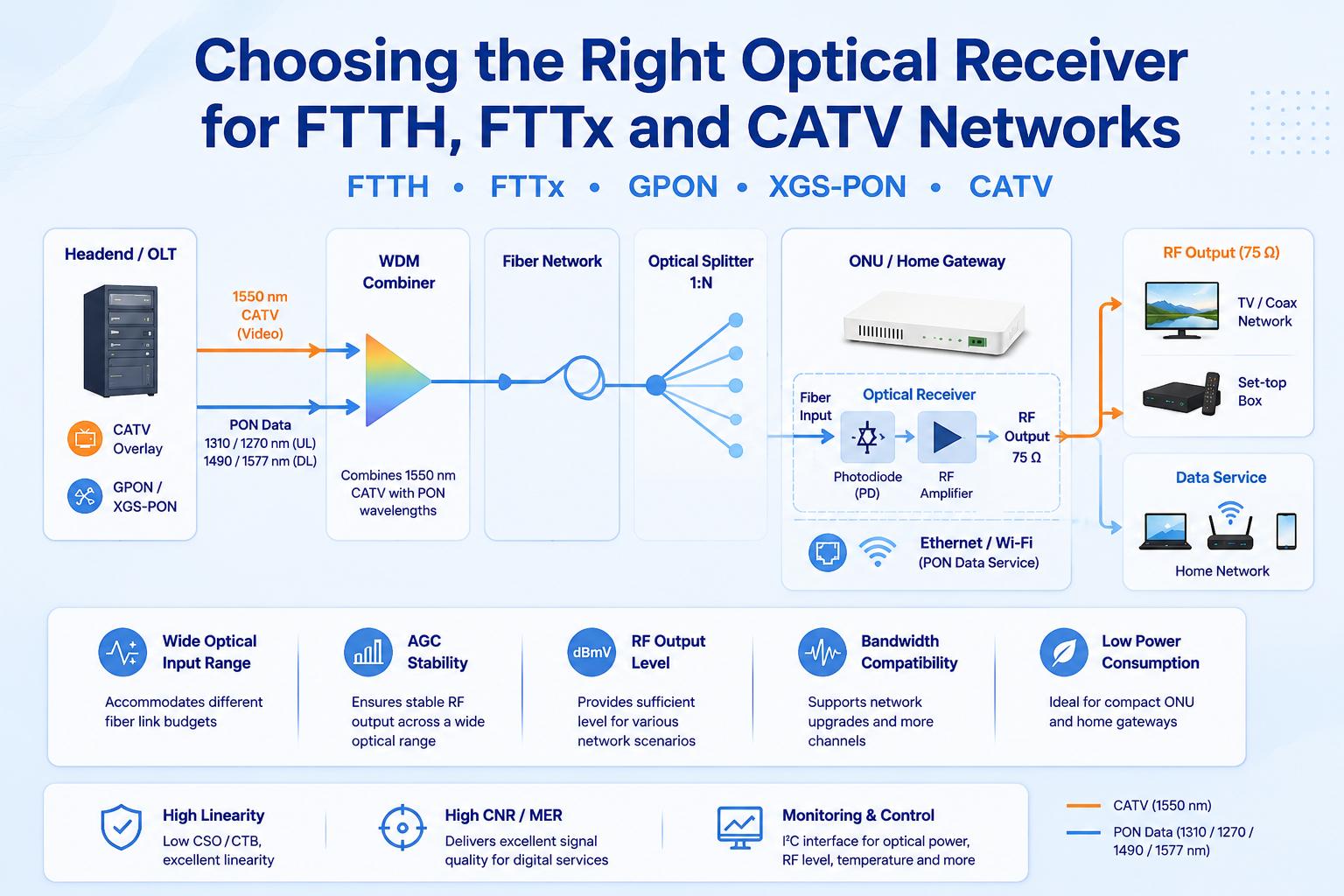
Fiber access networks are often discussed in terms of OLT capacity, split ratios, ONU performance and available bandwidth. However, when an operator also needs to deliver CATV or broadcast video over the same fiber infrastructure, the optical receiver becomes an equally important part of the system.
The receiver determines how the incoming optical video signal is converted into a usable RF output. Its optical input range, RF bandwidth, automatic gain control, linearity and power consumption can directly affect picture quality, network stability and the amount of field adjustment required.
Selecting an optical receiver should therefore begin with the network architecture and operating conditions—not with a single headline specification.
This guide explains the main factors to consider when choosing an optical receiver for FTTH, FTTB, GPON, XGS-PON and CATV distribution networks.
What Does an Optical Receiver Do in an FTTH/CATV Network?
In a CATV-over-fiber system, television or broadband RF signals are converted into optical signals at the headend and transported through the fiber network.
At the subscriber side, building distribution point or optical node, the optical receiver converts the incoming optical signal back into a 75-ohm RF signal. The RF output can then be connected to a television distribution network, set-top box, cable modem or other RF equipment.
In many FTTH deployments, CATV video is carried as an optical overlay alongside the PON data service. A wavelength division multiplexing device separates the optical video signal from the data wavelengths before the video signal reaches the photodiode and RF amplification stages.
It is important to distinguish a CATV optical receiver from an ONU or optical transceiver. An ONU terminates the PON data connection and provides services such as Ethernet, voice or Wi-Fi. A CATV optical receiver is responsible for recovering the analog RF spectrum used for television or other broadband RF services.
The two functions may be integrated into the same customer-premises device, but they remain separate signal paths with different performance requirements.
Start with the Network Architecture
Before comparing receiver specifications, define where and how the device will be used.
FTTH with CATV Overlay
In a residential FTTH network, the receiver is usually installed inside an ONU, gateway or compact external enclosure. Typical priorities include:
- Low power consumption
- Small module size
- Stable RF output
- Wide optical input range
- Integrated WDM and photodiode
- RF output enable or disable control
- Compatibility with GPON or XGS-PON equipment
Because the receiver may be installed inside a compact plastic enclosure, heat dissipation and current consumption can be as important as RF output level.
FTTB or Multi-Dwelling Unit Distribution
An FTTB receiver may serve multiple apartments or feed an internal coaxial distribution network. Compared with a single-home receiver, the system may require:
- Higher RF output capability
- Better linearity
- Sufficient level for splitters and in-building cable loss
- Wider RF bandwidth
- Reliable operation across a larger temperature range
The number of downstream RF channels and the total composite loading should be considered when evaluating output level and distortion.
CATV Optical Node or HFC Network
In an HFC or traditional CATV network, the receiver may be used inside an optical node, amplifier or distribution platform. These applications generally place more emphasis on:
- High RF output
- Low distortion
- Strong return loss
- Flat response across the operating band
- Stable performance under high channel loading
- Compatibility with existing coaxial infrastructure
A receiver intended for a compact FTTH ONU may not provide the output power required for an HFC optical node. Similarly, a high-output optical receiver designed for network infrastructure may consume more power than is practical for residential equipment.
Check the Optical Input Power Range
The optical input power range is one of the first parameters to verify. Received optical power depends on several factors:
- Transmitter output power
- Fiber attenuation
- Connector loss
- Splice loss
- WDM insertion loss
- Optical splitter ratio
- Installation margin
- Component aging
A receiver should operate correctly across the expected optical power range, not only at the nominal design point. The optical link budget should include both the minimum and maximum power that may reach the receiver. Excessive optical input can overload the photodiode or RF stages, while insufficient optical input can reduce carrier-to-noise performance.
A useful receiver specification should therefore define:
- Absolute optical input range
- Recommended operating range
- AGC operating range
- Optical overload limit
- RF performance at low optical input levels
The lowest detectable optical power is not necessarily the lowest level at which acceptable CATV performance can be maintained. Engineers should evaluate the required CNR or MER at the actual minimum operating power.
Understand the Role of AGC
Automatic gain control is especially useful in FTTH and FTTB deployments where received optical power may vary from one location to another.
Without AGC, a change in optical input power usually produces a corresponding change in RF output level. This can create inconsistent installation results and increase the need for external attenuators or manual adjustment.
An AGC optical receiver adjusts its internal gain or attenuation to maintain a relatively stable RF output within a specified optical power range. However, the presence of AGC alone is not enough. Engineers should compare:
- AGC input range
- Target RF output level
- Output variation across the AGC range
- Response to rapid optical power changes
- Behavior outside the AGC range
- Available AGC offset adjustment
- Noise and distortion at the edges of the range
A wider AGC range can reduce field adjustment, but performance should still be checked at both low and high optical input levels. At the low end of the optical range, noise becomes the main concern. At the high end, photodiode and amplifier linearity may become more important.
Match the RF Bandwidth to the Actual Service
The required RF bandwidth depends on the network standard and the services being transported. Common optical receiver bandwidths include:
- Approximately 40 or 47 MHz to 862 MHz
- Approximately 40 or 47 MHz to 1000 MHz
- Approximately 40 or 47 MHz to 1200 MHz
A wider bandwidth is not automatically better. It may increase cost, power consumption or design complexity without providing a practical benefit if the network only operates below 1 GHz. The receiver bandwidth should be selected according to:
- Current downstream frequency plan
- Number of analog and digital channels
- DOCSIS spectrum requirements
- Planned network upgrades
- Diplex filter configuration
- RF amplifier and tuner bandwidth
- Internal PCB and connector performance
For new equipment designs, some additional frequency margin may be useful. However, every component in the signal path—including the photodiode, amplifier, transformer, filter, PCB and connector—must support the intended frequency range.
Evaluate RF Output Level in System Context
RF output level should not be evaluated as an isolated number. A higher output level may be useful when the receiver must drive splitters, long coaxial cables or multiple subscriber outlets. However, producing a high composite output while maintaining low distortion requires sufficient linearity.
The required receiver output should be calculated from the downstream RF budget:
- Determine the required level at the television, tuner or cable modem.
- Add coaxial cable loss.
- Add splitter, tap and connector loss.
- Include installation and aging margin.
- Confirm that the receiver can provide the required composite level without exceeding its distortion limits.
For a compact FTTH ONU, an output around the level needed for one home may be appropriate. For FTTB or building distribution, a higher output level may be required.
Adding an external RF amplifier after an optical receiver can increase the output level, but it also affects noise, distortion, power consumption and system complexity. It is generally better to evaluate the complete RF chain during the design stage.
Compare CNR, CSO, CTB and Linearity
Optical receiver performance is normally described using several RF quality parameters.
Carrier-to-Noise Ratio (CNR)
Carrier-to-noise ratio indicates how clearly the RF carrier can be recovered above the noise floor.
CNR generally becomes more difficult to maintain as received optical power decreases. For this reason, the CNR test condition should always be checked. A CNR value without the corresponding optical input power, channel loading and measurement bandwidth is difficult to compare.
Composite Second Order and Composite Triple Beat
CSO and CTB describe intermodulation distortion generated when many RF channels are transmitted simultaneously.
These parameters are particularly important in networks carrying a large number of analog or QAM channels. Receiver linearity should be evaluated at the intended optical input power and RF output level.
MER for Digital Services
For digital QAM services, modulation error ratio is often a more direct measure of signal quality at the system level.
MER is affected by more than the optical receiver. The transmitter, fiber link, optical noise, receiver linearity, RF amplifier, impedance matching and test equipment all contribute to the final result.
A receiver with good CNR and distortion performance provides a stronger foundation, but the complete optical and RF link should still be tested using the intended channel plan.
Review Flatness and Output Return Loss
Amplitude flatness describes how much the RF output level changes across the operating frequency band. Poor flatness can create frequency-dependent signal levels, making it difficult to maintain consistent performance across all television and data channels.
Output return loss indicates how well the receiver is matched to the 75-ohm RF system. Poor impedance matching can cause reflections, ripple and interaction with downstream cables or filters.
When comparing modules, check whether flatness and return loss are specified across the full operating band rather than at only one frequency.
The final equipment design can also affect these parameters. PCB layout, grounding, connector placement, output matching and enclosure construction should therefore be included in prototype verification.
Consider Power Consumption and Thermal Design
Power consumption is especially important for integrated ONU and residential FTTH equipment. A module with lower current consumption can help:
- Reduce enclosure temperature
- Simplify power supply design
- Improve long-term component reliability
- Meet equipment energy targets
- Allow a smaller housing
- Reduce the thermal impact on nearby PON and Wi-Fi components
However, power should not be reduced at the expense of RF performance. Bias current, gain and linearity are closely related in many receiver designs.
Thermal testing should be performed inside the final enclosure, not only on an open evaluation board. The receiver may be located near processors, optical transceivers, power converters or Wi-Fi components that raise the internal temperature.
Decide Which Monitoring and Control Functions Are Needed
Basic optical receivers may provide only optical input and RF output connections. More integrated designs may include digital monitoring and control functions. Useful functions can include:
- Optical input power monitoring
- RF output level monitoring
- Temperature monitoring
- RF output enable or disable
- CATV service switching
- AGC offset adjustment
- I²C communication
- Alarm or diagnostic reporting
These features are useful in managed ONUs, operator gateways and remotely monitored network equipment. For example, optical power monitoring can help distinguish a fiber link problem from an RF distribution problem. RF output control can allow an operator to disable CATV service without interrupting the broadband data connection.
The value of these functions depends on whether the host system can read, store and act on the information. An I²C interface provides limited benefit if the equipment firmware does not support monitoring or control.
Integrated WDM or Separate Optical Components?
An FTTH CATV receiver may use an integrated WDM and photodiode assembly or separate optical components. An integrated design can offer:
- Smaller PCB area
- Fewer optical connections
- Simplified assembly
- Reduced insertion-loss variation
- Easier integration into compact ONU housings
A separate-component design may provide more flexibility in connector type, optical routing or replacement strategy. The choice depends on production volume, enclosure design, assembly process and optical interface requirements.
Connector selection should also be confirmed early. SC/APC and FC/APC interfaces are commonly used where low optical reflection is important, while other connector options may be required for specific equipment platforms.
A Practical Selection Matrix
| Deployment | Main Priorities | Useful Receiver Features |
| Single-family FTTH | Low power, compact size, stable output | AGC, integrated WDM/PD, 5 V operation, RF on/off |
| GPON or XGS-PON ONU | Easy system integration and diagnostics | I²C, optical power monitoring, temperature monitoring |
| FTTB or MDU | Higher output and good linearity | Wide bandwidth, strong CNR, low CSO/CTB |
| CATV optical node | High composite output and RF stability | High linearity, good flatness, strong return loss |
| Managed operator CPE | Remote service control | RF enable/disable, AGC offset, status monitoring |
| Cost-sensitive basic receiver | Simple RF conversion | Fixed-gain or basic AGC architecture |
Note: This table should be used as a starting point rather than a replacement for a full optical and RF link budget.
Common Optical Receiver Selection Mistakes
Selecting Only by Maximum Bandwidth
A receiver with the widest frequency range may not provide the best power consumption, cost or performance for a network operating below 1 GHz.
Comparing RF Output Without Checking Test Conditions
Output level should be reviewed together with optical input power, channel loading, distortion and AGC status.
Ignoring the Maximum Optical Input
Designers often focus on sensitivity but overlook overload conditions. A short fiber path or low splitter ratio can produce a higher optical level than expected.
Treating AGC as a Universal Solution
AGC stabilizes output only within its specified operating range. It cannot compensate for a severely underpowered optical link or an overloaded photodiode.
Ignoring the Final Enclosure
Receiver performance measured on an evaluation board may change after installation in a compact housing with limited airflow and nearby heat sources.
Using Typical Values as Guaranteed Limits
Typical performance is useful for evaluation, but production design should be based on guaranteed minimum and maximum limits where available.
Commissioning Checklist
Before approving an optical receiver for deployment, verify the following:
- Optical input power at minimum, nominal and maximum link conditions
- RF output level across the AGC range
- Frequency response across the full service band
- CNR or MER at the lowest expected optical input
- CSO and CTB under the intended channel loading
- Output return loss with the final PCB and connector
- Power consumption at the required supply voltage
- Thermal performance inside the final enclosure
- RF on/off and control-interface behavior
- Optical and RF monitoring accuracy
- Startup, shutdown and optical reconnect behavior
- Performance over the required temperature range
Testing should use a representative transmitter, channel plan, optical loss and downstream RF load. A single-tone laboratory test is not sufficient to represent a fully loaded CATV system.
Frequently Asked Questions
What is the difference between an FTTH optical receiver and an ONU?
An ONU terminates the PON data service, while a CATV optical receiver converts an optical video signal into an RF output. Both functions can be integrated into the same device.
Why is AGC important in an FTTH CATV receiver?
AGC helps maintain a stable RF output when optical input power varies between subscriber locations. This can reduce manual adjustment and improve installation consistency.
Can the same optical receiver be used for GPON and XGS-PON?
The CATV receiver path may be used alongside either GPON or XGS-PON when the optical architecture, WDM arrangement and host equipment are designed for the relevant system. Compatibility should be verified at the complete equipment level.
Does lower optical sensitivity always mean better performance?
No. Sensitivity must be considered together with CNR, RF output level, distortion and the receiver’s AGC range. A receiver may detect a weak optical signal without delivering the RF quality required by the network.
Should an FTTH receiver support 1.2 GHz?
That depends on the network frequency plan and upgrade roadmap. A 1.2 GHz receiver can provide additional spectrum margin, but the transmitter, RF amplifiers, filters, PCB and subscriber equipment must also support the wider band.
Final Considerations
Choosing an optical receiver is a system-level decision. Optical input power, AGC range, RF bandwidth, output level, noise, distortion, power consumption and control functions should all be evaluated against the actual deployment environment.
For a compact FTTH ONU, low power and stable AGC operation may be the main priorities. For FTTB or CATV distribution, output capability and linearity may carry more weight. Managed operator equipment may also require optical monitoring, temperature reporting and remote RF control.
SANLAND’s current product structure includes CATV optical receiver modules for GPON and XGS-PON equipment, compact AGC receiver modules, conventional CATV optical receiver modules, ONU products and related FTTx components. These categories can be used as reference points when comparing architectures and defining the receiver specifications required for a particular network.